Learn - Aug. 13, 2023
Low-temperature methanol washing process is a chemical process used for gas purification. In 1954, the Luigi Company built the first low-temperature methanol process unit in Sasol, South Africa, and since then, this process has been more than 70 years. Low-temperature methanol process is also known as Rectisol, which is used in gas purification units such as ammonia synthesis, methanol synthesis, coal-to-oil, coal-to-gas, industrial hydrogen production or natural gas desulfurization.
1. After the conversion gas enters the device, it is cooled by heat exchange, separated from water, and then enters the scrubber for desulfurization washing by CO2-rich methanol solution, removing H2 S, part of CO2 and other components, and then washed by lean methanol solution for decarbonization until CO2 ≤ 10 mg/L. After heat exchange, the cold capacity is recovered and sent to the PSA device.
2. The unconverted gas is cooled, washed with ammonia, and then washed by low temperature methanol system to desulfurize and decarbonize. After the heat exchange temperature rises to 30 ℃, it is sent to the cryogenic separation process. The rich methanol from the decarbonized section is pumped up to 4.5MPa, and after cooling, part of the rich methanol can be used again.
3. The methanol solution from the desulphurization and decarbonization section is cooled by heat exchange and reduced pressure, and then dissolved by flash evaporation in the tank. The flash gas is pressurized by a circulating gas compressor and returned to the feedstock gas, while the useful gas is recovered.
4. The flash gas in the tank passes into the lower section of the tower, the liquid is pressed by pump, and after heating up, the gas is lifted by low-pressure nitrogen. The methanol is heated up with the lean methanol from the thermal regeneration tower after the pressure is raised by the pump.
5. The high-temperature lean methanol is cooled by heat exchange, pumped and pressurized through the lean methanol tank, and sent to the top of the scrubber by heat exchange and cooling as an absorber to complete the methanol cycle.
Low temperature methanol washing is a kind of purification process in chemical plant by physical absorption of acid gas. This process has the advantages of low energy consumption, stable operation and low raw materials. Among whole process, the lean methanol pump is the key equipment, which is the power unit for desulfurization and decarbonization gas purification.
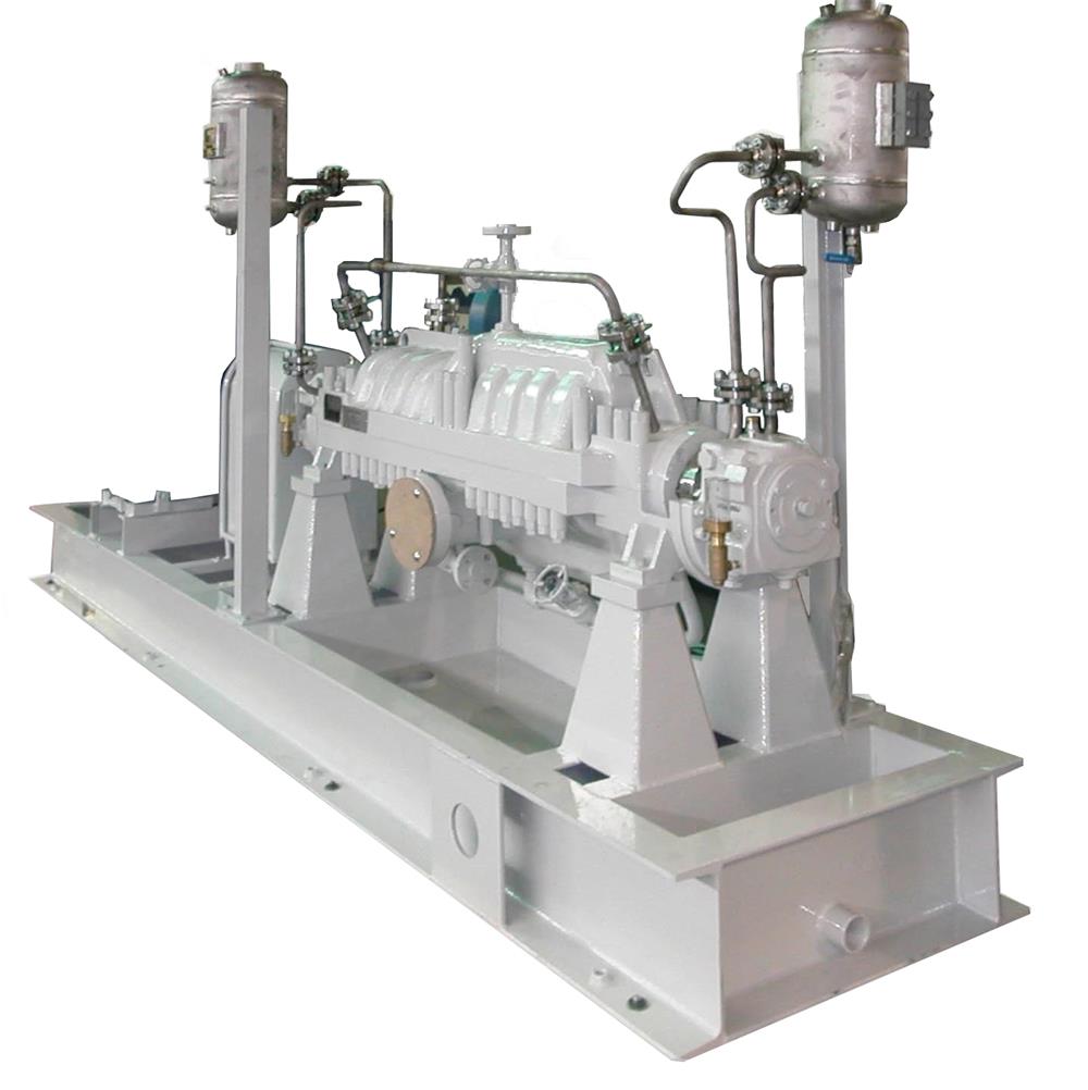
The lean methanol liquid pump is an important equipment in Rectisol, which is responsible for the transportation of lean methanol in washing raw gas. The main function of the pump is to cool the hot methanol from the regenerator through heat exchange, wash and purify the acid gas, and send it to the scrubber for selective purification of desulfurization and decarbonization stage. Lean methanol liquid pumps mostly select horizontal multistage centrifugal pumps with middle split casing, which are also know as BB3 axially split multistage pumps. This article is a detailed introduction of BB3 axially split multi-stage pump.
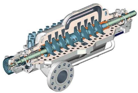
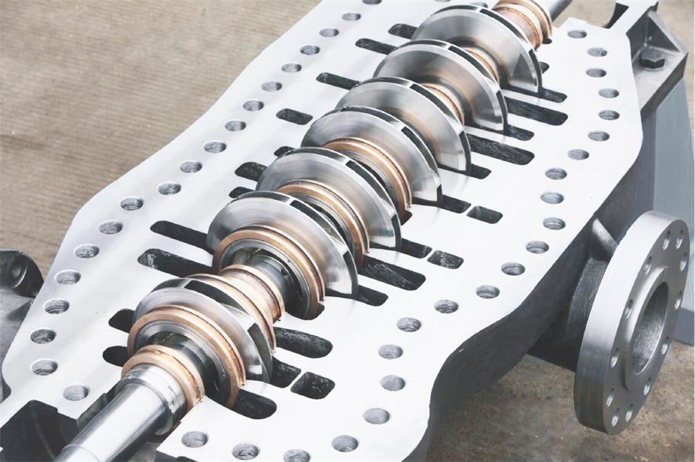
The BB3 axially split multi-stage centrifugal pump is composed of three main components: rotor components, pump housing and bearings. The pump casing is designed into two parts, open the upper pump casing, then could see all the structures inside the pump, easy maintenance. The overall structure of the axially split case multi-stage centrifugal pump is supported at both ends. The bearings at the driving end are used to bear the weight of the rotor and the radial force of the pump. The non-driving end is a group of angular contact ball bearings, which are used to bear the remaining radial force and axial force.

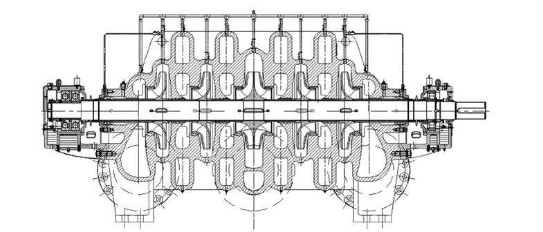
The BB3 axially split multistage pump has the advantages of large flow rate, high head and wide efficient area. The hydraulic components include impellers, a suction chamber, a pressurized water chamber and a transition flow channel. The transition flow channel could be divided into long transition flow channel and short transition flow channel according to the different structure arrangement. When the axially split multi-stage pump is used in the condition of large capacity, the double runner structure is arranged in 180 degrees symmetry, which could automatically balance the radial force generated by the impellers and could operate smoothly. The volute flow channel is designed into two symmetrical flow paths, the transition flow channel adopts the form of double flow channel, and the volute adopts the form of double volute, which be better balance the radial force of the multistage pump.
We divide the transition flow channel of the axially split multistage pump into three parts to describe, which are the forward channel, the bridge and the reverse channel:
The forward channel part is similar to the pressurized water chamber, and its role is to collect the fluid flowing from the impellers, convert the velocity energy of the fluid into pressure energy, and deliver it to the middle transition part. In order to balance the radial force of the pump, the forward channel design uses a symmetrical arrangement of two channels at 180°.
In order to reduce the loss of energy in the intermediate transition segment, the velocity energy of the fluid should be further converted into pressure energy.
The function of the reverse channel is to introduce the fluid to the next impeller and reduce the hydraulic loss.
1. Impellers are made from stainless steel or duplex stainless steel (SS304,SS316,SS316L,2205,2507 ), which has excellent performance of corrosion resistance and cavitation resistance. The first stage impeller adopts double suction and closed impeller. The secondary impeller adopts type of single suction, closed, high efficiency, symmetrical arrangement. Each impeller and the shaft are connected by a key, and the coordination between the shaft and each impeller is interference, and the interference amount is 0.03mm ~ 0.04mm. Each impeller is positioned independently with clasp rings.

2. The hydraulic design of the pump body, pump cover suction chamber, transition passage and extrusion chamber is integrated, and the pump body and pump cover are separated along the split face. The transitional flow channel adopts symmetrical vortex shell design, and the pump body and the pump cover each have a water outlet. High pressure asbestos gasket is used to seal between pump body and pump cover and is tightened by cap nut.
3. Pump body seal ring/impeller seal ring. The sealing ring of the impeller is fixed with cylindrical head screws; All sealing rings are made from high wear-resistant and high hardness materials.
4. Shaft. Shaft is rigid design. The size design of the shaft decreases step by step from the middle to both sides, and each level decreases by 0.125 mm; Shaft surface chromium plating 0.05mm ~ 0.08mm.
5. Throttle shaft sleeve and throttle sleeve.The throttle shaft sleeve is installed at the suction entrance of the impeller on the non-drive side, and is connected with the shaft by a key. The throttling sleeve is installed on the pump body and forms a small gap with the throttling sleeve. The axial force on both sides of the gap is generated by the pressure difference and points to the non-driving side.
6. Bearings. Both ends of the sliding bearings using plain bearings, can better withstand the radial load.

