Author: Li Yun (client of ZGPV)-Senior Equipment Manager, 25+ Years in Heavy Chemical Processing -Jul. 27, 2026
Content Index
- CHAPTER 1: THE OPERATING ENVIRONMENT OF CENTRIFUGAL PUMPS IN CHEMICAL PLANTS
- CHAPTER 2: MATERIAL SELECTION OF CENTRIFUGAL PUMPS
- CHAPTER 3: HYDRAULIC MODEL SELECTION OF CENTRIFUGAL PUMPS
- CHAPTER 4: STRUCTURE & CONSTRUCTION OF CENTRIFUGAL PUMPS
- CHAPTER 5: MECHANICAL SEALS & FLUSHING PLANS OF CENTRIFUGAL PUMPS
- CHAPTER 6: INSTALLATION & COMMISSIONING OF CENTRIFUGAL PUMPS
- CHAPTER 7: OPERATIONAL MONITORING OF CENTRIFUGAL PUMPS
- CHAPTER 8: MAINTENANCE PRACTICES TO PROLONG CENTRIFUGAL PUMP LIFE
- CHAPTER 9: AVOIDING COMMON MISTAKES IN OPERATION OF CENTRIFUGAL PUMPS
- CHAPTER 10: ECONOMICS: THE TOTAL COST OF OWNERSHIP OF CENTRIFUGAL PUMPS
- CHAPTER 11: EMERGENCY HANDLING OF CENTRIFUGAL PUMPS
- CONCLUSION: RELIABILITY IS THE ESSENTIALITY OF CENTRIFUGAL PUMPS
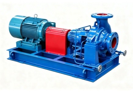
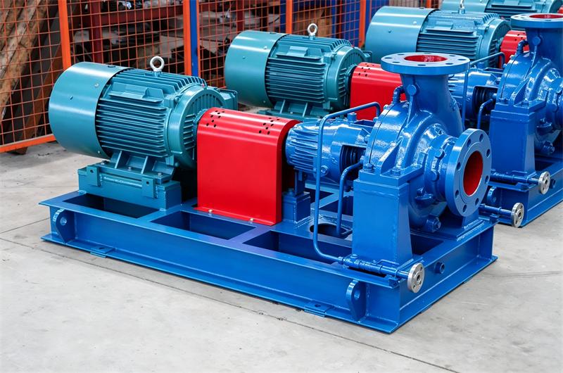
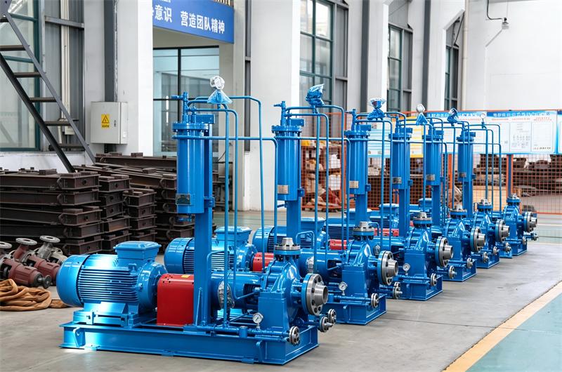
Direct Answer: A centrifugal pump is a commonly found hydraulic pumping device which is designed and manufactured to move the water or other types of fluids by converting the mechanical rotation into fluid pressure. The main parts of a centrifugal pump consist of impeller(s), casing, shaft, sealing, bearings, bearings housing, couplings, driving unit and base plate.
When the fluid enters the pump suction and arrives the center eye of the impeller, the centrifugal force generated by the high speed starts to throw it outward of the impeller passage, its speed and pressure are increased simultaneously. At last, with the restriction of the pump casing, the velocity created by the impeller is converted into the pressure and then discharged to through the outlet of pump.

This guide is meant to take you through the full lifecycle of centrifugal pumps used in chlor-alkali services. We may start with early material selection, then hydraulic sizing, then installation and commissioning, and later we move into daily operation, plus the longer-horizon maintenance side. It's based on know-how drawn from real operating practice in plants, along with specific case studies-some that went well and others that didn't. A number of practical principles of those chemical pumps are covered right here below.
And this guide reflects the I knowledge accumulated and lessons I gained from over two decades of managing centrifugal pumps as well as other rotating equipment in chlor-alkali facilities across China. As concerns the operating conditions in industrial processing, the chlor-alkali industry is generally regarded as the harshest one. Near-boiling saturated brine and pharmaceutically purified caustic soda, as well as wet chlorine gas that can attack and destroy standard metallurgical materials of general centrifugal pumps within hours of exposure.
The centrifugal pump is the mainstay of this industry. A single membrane cell room may accommodate fifty or more pumps taking care of multiple functions, including brine feed, anolyte circulation, catholyte transfer, chlorine drying, sulfuric acid circulation, and sundry auxiliary services. As a result, the immense cost of a pump fleet nowadays often exceeds several million dollars, with its collective energy consumption accounting for 15-20% of the entire plant's electrical load.
Still, the selection of a chemical centrifugal pump, as a kind of strategic link, hasn't been given enough weight, and too often it's been handled like just routine purchasing stuff. In my view, I have seen multiple plants where the centrifugal pumps at first looked cheap, say just a few thousand dollars each, but then somehow in only two years they turned into maintenance expenses that were about ten times that amount. And that's not even counting the less visible costs, like lost production output and the safety risks that quietly accumulate.
Before picking out the centrifugal pumps properly, we really need to make sure, carefully, the fluids involved in the chlor-alkali process because distinct issues can pop up, especially once you're looking at three main fluid streams either via membrane technology or diaphragm tech.


Brine is really the main feedstock. Usually it comes as either rock salt, or as a solution mined brine that already sits at around 26-28% NaCl in a saturated kind of state. Then the brine is heated up to about 80-95°C so that conductivity goes up and the cell voltage can come down, or so it helps. After that the chloride ion activity becomes, sort of, more reactive in general.
Because you get the combined effect of high chloride concentration, higher temperature, and dissolved oxygen, you end up with an atmosphere that is basically friendly to pitting and stress corrosion cracking (SCC). Pitting happens when the passive oxide film on the stainless steel gets locally damaged, then you get a tiny anode spot, while the rest of the passive surface behaves like a big cathode. The high current density produced by the process can then drive fast localized metal loss. SCC requires tensile stress, either one that's applied or just residual, plus a corrosive environment at the same time, and that combo can lead to a sudden failure without any kind of warning, not even a hint.
As you may be aware that the brine solution, especially at high temperature, is extremely corrosive to the stainless steel, thus the proper material selection of centrifugal pumps is essential for long service life of those pumping devices.
The anolyte is basically the electrolyte that leaves the anode compartment of the electrolysis cell, kind of like the stuff after it's passed through. It is depleted in sodium chloride, with a usual concentration around 18-22% but it is also saturated with chlorine gas and acidified so the pH ends up near 2-4. Its temperature is pretty much similar to that of the incoming feed brine, no big change. The anolyte is subjected to the combined effects of severe chloride attack from brine, the oxidizing ability of dissolved chlorine, and the corrosivity of low pH, which, in many cases, can make its environment too difficult for duplex stainless steels. What's more, the acidic condition might exert a destructive influence on the protective passive film of many common alloys that used in the chemical centrifugal pumps.
When you're adopting membrane cell technology, the anolyte ought to be without heavy metal ions , especially iron and chromium, because these impurities could deactivate the pricey ion-exchange membranes. And this firm cleanliness rule doesn't just stop at the anolyte itself, it also shows up for every wetted part in the anolyte circulation centrifugal pumps.
The catholyte is basically the sodium hydroxide solution, often held around 32% or 50% concentration and run at 80–90°C, it leaves the cathode compartment after that. Since it is the main product coming out of the process, it has to meet pretty strict purity criteria before it can be sold.
Compared with chloride-containing media, caustic soda is less corrosive to many metallic materials; however, it has its own challenges. For example, under high concentrations and temperatures, caustic soda may result in caustic embrittlement of carbon steel. More importantly, its tendency to crystallize won't be diminished by decreasing temperature, potentially leading to blockage of seal chambers and damage to mechanical seals of centrifugal pumps
As for its purity criterion, the catholyte must be completely iron-free; otherwise, the iron residue will impede the generation of qualified and saleable caustic product. Therefore, either the use of nickel-based alloys chemical pumps or fully lined pumps is required compulsorily.
The wet chlorine gas that comes out from the cell anodes really has to be dried and then compressed, before it can be liquefied or sent to any downstream processing. For the drying stage, they usually use concentrated sulfuric acid, commonly around 93-98% concentration, and the whole thing gets done in packed towers.
It is noted that the combination of chlorine gas and moisture will produce hypochlorous and hydrochloric acids that are highly corrosive. For instance, even titanium centrifugal pumps, normally the priority for oxidizing services, is still susceptible to erosion when the moisture content is too high. Additionally, the sulfuric acid applied in the drying towers is also corrosive, especially at the extremely high temperatures caused by the absorption reaction.


Throughout the entire chemical pump selection in many plants, what fundamentally distinguishes the lifecycle of one pump from another is the metallurgy material, and the discrepancy in serviceability and endurability, from my own observation, can range from six to twenty years.
What deserves mentioning is that, under no circumstance should the 316L stainless steel be used for any wetted part in the centrifugal pumps during chlor-alkali service. Because the chloride concentration in our process is an order of magnitude higher than the maximum level that 316L can tolerate. Due to engineers' unfamiliarity with severe chlor-alkali environments, one typical yet unignorable mistake, as far as I am concerned, is that 316L at 60°C and 100,000 ppm chloride will suffer pitting within only a few days and will often fail catastrophically by SCC within several weeks. Subsequently, some bad outcomes I witnessed can be, such as cracked pump casings, fractured impellers, damaged mechanical seals, and, if worsened, plant shutdowns and serious safety risks.
For brine handling at moderate temperatures, up to around 100°C, duplex stainless steels are like an ideal option for centrifugal pumps, really. They have a two phase microstructure, with something close to equal shares of ferrite and austenite.
| Grade | UNS Number | PREN Value* | Pitting Resistance | SCC Resistance | Cost Factor |
| 2205 | S31803 | 32-36 | Good | Good | 1.0 (baseline) |
| 2507 | S32750 | 38-42 | Excellent | Excellent | 1.45 |
| CD4MCu | J93372 | 30-35 | Good | Good | 1.2 |
*PREN = Pitting Resistance Equivalent Number. Higher is better for chloride resistance.
Super Duplex 2507 is kind of an optimum choice for brine and anolyte chemical pumps , mainly because it has that high chromium level around 25% , plus molybdenum at about 3.8% and nitrogen near 0.28%. Together these elements sort of team up to give really strong resistance to pitting and crevice corrosion, even when the chemistry is harsh. In a recent plant retrofit, we swapped out the old 316L brine centrifugal pumps and installed 2507 super duplex stainless steel pumps instead. The 316L units might last roughly 18 months on average before they need major maintenance. By contrast , after five years the 2507 centrifugal pumps can still run basically as if they are new, and we didn't see any meaningful corrosion. Sure, the original capital cost is more than 40% higher, but the payback period from the lifecycle cost analysis can come in at only about 16 months. This happens mainly because there's less maintenance work, less downtime overall, and the pumps keep performing longer.
Super duplex performs well in chlorides; however, it has limited resistance to strong acids. The anolyte stream presenting a pH of 2 to 4 is at the borderline of duplex suitability. For anolyte circulation, we often use titanium alloys made centrifugal pumps.
Titanium can form a highly stable, tenacious oxide film to resist attack from the combination of chlorides and acid. Also, in oxidizing environments, its passivity is nearly perfect. Thus, Titanium centrifugal pumps are considered optimal for the anolyte environment.
Although CP (commercially pure) titanium, Grade 2, can cater for many anolyte requirements, when there is any risk of reducing conditions, Grade 7 titanium containing 0.12-0.25% palladium will be specified. With palladium addition, chemical corrosion resistance in reducing acids and additional margin of safety can be remarkably enhanced.
Titanium is vulnerable to attack by fluorides and concentrated reducing acids, and also has poor performance when encountering crevice corrosion in hot chloride solutions and depleted oxygen. So reasonable design of seal chambers and gasket surfaces of centrifugal pumps is consequential to avoid crevices.
However, titanium centrifugal pumps are so expensive that they might cost 2-3 times what a 316L pump costs, but the expense proves justifiable when it comes to the reliability in anolyte service.
To obtain absolutely pure product, nickel chemical centrifugal pumps are preferred. In particular, high-purity nickel, grade 200 or 201, not only shows great tolerance to caustic soda at all concentrations and temperatures in the chlor-alkali process, but also prevent product from the introduction of iron contamination.
On one hand, carbon steel could withstand the caustic environment itself. On the other hand, it would release an amount of iron in the meantime. Stainless steels also impurify the product to some degree. However, Nickel outperforms other materials in terms of its perfect corrosion resistance and product purity.
As regards Nickel 201, the low carbon grade, it is used for temperatures above 600°F (315°C) that well beyond the operating temperatures of our process. Even so, to be conservative, we still specify Nickel Grade 200 for catholyte centrifugal pumps.
The high silicon cast iron, where the 14-16% silicon fraction gives it very strong resistance to concentrated sulphuric acid at high temperature, is suitable for the sulfuric acid drying circuit even though it behaves brittle, fragile, kind of awkward at times. Thus, high silicon cast iron made centrifugal pumps are widely used in conveying of high temperature sulfuric acids.
Ceramic liquid ring vacuum pumps as standardized choices are applied to wet chlorine gas pumping. The ceramic components are typically alumina or silicon carbide, so they are virtually inert to chlorine attack. Further, the liquid ring design using concentrated sulfuric acid as seal liquid creates commendable sealing capability, without contacting the chlorine gas with any material that could be corroded.
Just as material selection is important to corrosion precaution, hydraulic selection of chemical pumps also plays an undeniable role in avoiding performance failure.
That pump performance curve is kind of the most important document in the selection, because it shows the relationship between flow rate, head (pressure) , power consumption and the efficiency. Every pump has its own design point, it's often named Best Efficiency Point BEP, where the hydraulic design is kind of optimally balanced. Below are a few of the key parameters, you really see them there. Flow rate Q is usually given in gallons per minute (gpm) or in cubic meters per hour (m³/h). Total Dynamic Head TDH indicates the total pressure the centrifugal pump has to produce, and it's commonly written as feet or meters of liquid column. NPSH Required NPSHR shows the minimum suction pressure needed so cavitation doesn't happen. Efficiency η is the ratio of hydraulic power output, to the shaft power input.
This is probably the most frequently violated rule in centrifugal pump operation. When a pump operates at its BEP, internal recirculation is minimized; radial loads and vibration remain the lowest. Once the operating point moves away from BEP, the hydraulic conditions inside the pump deteriorate.
See the table below; it shows the effect of operation away from BEP:
| Operating Condition | Effect | Consequence |
| <80% of BEP | Recirculation at impeller eye | Increased NPSHR, cavitation, shaft vibration |
| >110% of BEP | Recirculation at impeller periphery | Noise, vibration, potential overload |
| Beyond shutoff | No flow, hydraulic recirculation | Rapid temperature rise, seal failure |
| Far to right of BEP | Net positive suction head drop | Cavitation damage to impeller |
Consider, for example, in one of our plants, we had a brine transfer centrifugal pump operating at 60% of its BEP. Severe vibration occurred, and the bearings had to be replaced every three months. After extensive troubleshooting, we discovered the pump had been oversized during the original engineering phase. When a variable frequency drive was installed, the chemical pump speed was reduced until the operating point reached around 90% of the BEP, and the disappearing vibration was accompanied by over two years of extended bearing life.
Net Positive Suction Head (NPSH) is basically the gap between the suction pressure right at the pump inlet and the liquid's vapor pressure, sort of like a measure of how much "push energy" is on hand to shove liquid into the pump without letting it flash. Net Positive Suction Head Available (NPSHA) comes from the plant piping system and whatever conditions are there, while Net Positive Suction Head Required (NPSHR) is what the centrifugal pump design needs.
As a rule of thumb, NPSHA should be higher than NPSHR, usually by something like 1–3 feet (0.3–1 meter), and if it isn't then vaporization starts at the impeller eye, which means bubbles form and later collapse quite violently when they meet higher pressure zones. This thing is called cavitation. It can throw off microjets of liquid that cause erosion type damage, which drags down efficiency and can eventually ruin the impeller of a chemical process pump. Common NPSH problems in chlor-alkali plants are as follows. Both brine with high dissolved gas content and hot fluids, or high vapor pressure, can lead to lower NPSHA. And undersized piping or clogged strainers will also cause insufficient suction volume.
Oversizing a centrifugal pump is perhaps the most common mistake in pump selection. Engineers often specify for worst-case conditions; however, the plant operates at typical conditions. It turns out that a pump might be chronically throttled, operating away from its BEP, and finally wasting energy.
To cope with that, with VFD, we can reduce both flow rate and head, moving the operating point closer to the BEP and significantly reducing power consumption by reducing pump speed. As shown, this relationship is governed by the Affinity Laws.
Q1/Q2 =N1/N2
H1/H2 =(N1/N2 )2
P1/P2 =(N1/N2 )3
The cubic relationship between speed and power means that even a 10% speed reduction yields a 27% power reduction. In one plant, we installed VFDs on twenty brine circulation centrifugal pumps, and then the energy consumption dropped by 25%, recovering the VFD investment in less than two years.


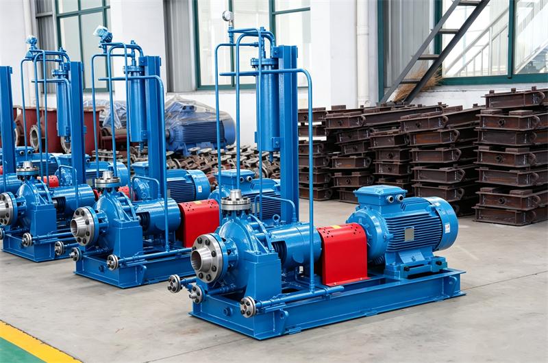
Although there are various types of centrifugal pumps, but a back pull-out design is considered mandatory for standard chemical process pump in a chlor-alkali plant. This means the bearing housing, shaft, impeller, and seal assembly can be removed as a single unit for service, without disturbing the piping connections. By adopting this approach, especially in some plants where the end suction centrifugal pumps often require seal replacements, hours of labor can be saved and downtime can be shortened considerably.
The casing of a centrifugal pump itself is generally a single-stage volute design where the volute, the spiral-shaped casing, can lower the high-velocity and heighten the low-pressure. This process occurs when liquid leaves the centrifugal impeller to discharge through the nozzle.
| Impeller Type | Suitable For | Advantages | Disadvantages |
| Closed | Clean liquids (brine, caustic) | Highest efficiency, stable performance | Not suitable for slurries |
| Semi-open | Liquids with small solids | Good efficiency, handles some solids | More sensitive to wear |
| Open | Slurries,viscous fluids | Certain Solids handling | Lower efficiency |
| Recessed | Heavy slurries | Big amount solid handling | Lowest efficiency |
Service will always dictate the impeller type. In most cases concerning brine cleaning and caustic services, we use centrifugal pumps with closed impellers, whereas in the brine purification process where there may be calcium carbonate or magnesium hydroxide slurries, we use slurry type chemical centrifugal pumps with open or semi-open designs and a wear plate.

Although there a lot of centrifugal pump parts, but the shaft serves as a principal structural component of the rotating assembly. Deflection, or runout, at the seal chamber is a chief reason for mechanical seal failure. One noteworthy thing is that a flexible shaft permits the seal faces to separate, thus inducing leakage and rapid seal destruction.
For Heavy-duty shaft criteria, the criteria below must be met. First, at the seal chamber, the diameter should be at its minimum of 1.5 inches, namely 38 mm, for small centrifugal pumps, and shaft deflection shall be 0.002 inches or 0.05 mm at its maximum in all operating conditions. Also, the spacing of bearings needs to be as close as possible to shorten the span length.
Only by manufacturing the shaft from the same corrosion-resistant material as the wetted components, or at the very least, by fitting a corrosion-resistant sleeve at the seal chamber, can long-term reliability be achieved.
Few failure modes in centrifugal pumps are more common than bearing failure. The contributors usually lie in contamination of the lubricant, overheating, or excessive load from misalignment or operation away from BEP.
Two bearing types are available. One is ball bearings used in smaller pumps, suitable for moderate loads; the other is roller bearings applied in larger ones, usually withstanding higher radial loads.
The bearing housing of a centrifugal pump should be fitted with labyrinth seals or magnetic seals so as to prevent contamination. Besides, an oil level visible through a sight glass and a breather installed should be ensured to avoid pressure buildup. In high-temperature services, forced oil circulation or water cooling for the bearing housing is always specified.
One point I have often held is that a mechanical seal is only as good as the environment it operates in, sort of directly. In chlor-alkali service this idea is amplified tenfold. No other part or component is more prone to failure than the mechanical seal of centrifugal pumps, yet the annoying part is:, its failure very often brings the worst consequences: chlorine or caustic soda leaking out, which in turn creates safety risks and also environmental hazards.
A mechanical seal of a centrifugal pump, has two very polished faces, one that moves with the shaft, usually called the primary ring, and the other stays put inside the pump casing, this one is known as the mating ring. Those faces are pushed toward each other by spring force as well as hydraulic pressure, so you get a sealing interface that still lets a tiny leakage of liquid go through, more like a controlled micro seep. For a properly well-hermetic seal, this "leakage rate" generally ends up under 5 milliliters per hour.
Five failure modes exist here. First, abrasion of the faces might occur when solid particles in the process fluid get between the faces, acting as a lapping compound. Secondly, sudden temperature changes may distort the faces and thus open a leakage path; this is what we call thermal shock. Third, the seal materials like faces, springs, or elastomers, are vulnerable to chemical corrosion. Fourth, process fluid evaporating on the atmospheric side can form crystals that jam the seal. Fifth, it's hard to ensure the seal's design limits within an appropriate range if the pressure or temperature is too high for the centrifugal pumps


Standardized by the American Petroleum Institute as 682, a systematic method for describing seal flushing arrangements is provided. The importance of selecting the correct flush plan cannot be eclipsed by the sealing itself.
| Flush Plan | Description | Application in Chlor-Alkali Industries |
| Plan 01 | Internal recirculation from discharge to seal chamber | Clean services with low vapor pressure |
| Plan 11 | Recirculation from discharge with orifice | General-purpose, clean services |
| Plan 21 | Recirculation with cooler | Hot services (brine, anolyte) |
| Plan 23 | Recirculation from seal chamber through cooler | High-temperature, volatile services |
| Plan 31 | Recirculation with cyclone separator | Services with solids (slurry) |
| Plan 54 | External flush from clean source | CRITICAL – dirty, corrosive, crystallizin |
| Plan 52 | Unpressurized dual seal with buffer fluid | Toxic/hazardous fluids (chlorine) |
| Plan 53 | Pressurized dual seal with barrier fluid | Highest reliability for hazardous fluids |
| Plan 62 | Quench to atmospheric side | Services prone to crystallization (brine, caustic) |
Plan 32 is the key to chlor-alkali plants. It injects a clean, compatible fluid from an external source directly into the seal chamber of centrifugal pump. This flush fluid washes away corrosive species, dilutes concentrated salts to inhibit crystallization, and provides cooling and lubrication to the seal faces.
For Plan 32 to work right, a few things matter, not just one or two. First, the flush fluid itself has to be compatible with the process fluid, even when conditions change. So, in brine service, we typically stick with clean, diluted brine or condensate, but if it's caustic service, then a diluted caustic solution is the one people usually go with. Also, we generally keep the pressure around 15–30 psi (1–2 bar) above the seal chamber pressure, so the flow actually goes into the centrifugal pump. Then the temperature has to be kept within about 20°F (10°C) of the process temperature, otherwise you risk some thermal shock, which is never fun. And last, but not least, the flush rate should be governed with a flow control orifice , so it doesn't wander off like a loose idea. The effect of sealing warrants one thing that Plan 32 should always be used in combination with a close-clearance throttle bushing. By restricting the flow of process fluid from the impeller toward the seal, this bushing allows for the domination of flush fluid over the environment within the seal chamber of chemical centrifugal pump
From the lens of cost, Plan 32 needs a reliable external fluid source and a small pumping system. The operating cost may be $1,000 per pump per year; however, if left unprotected, the cost of seal failures in these services can unfortunately exceed $10,000 per year per pump.
It is indispensable that Plan 62 should be adopted when a single seal is used in a service crystallization, such as brine, caustic, or sodium sulfate. A quench fluid, usually low-pressure steam or water, is injected at the atmospheric side of the seal. This fluid washes away any crystals that form, in case of jamming the seal components and accelerating wear in the centrifugal pumps
Compatibility between the quench fluid and what the process is doing is basically paramount. If the seal fails, then the quench fluid may, at some point, get in contact with the process liquid, and because of incompatibility this could start a reaction or, more quietly, lead to contamination. For brine service, people often end up using water or steam, just as a rule of thumb ; for caustic service, condensate or a diluted caustic solution is the one that’s usually preferred.
Services involving chlorine, mercury, or other toxic materials recommend dual seals arranged in series, with a barrier fluid between them. The barrier fluid is maintained at a pressure so that flow across the inboard seal into the process, or across the outboard seal to a collection system.
Centrifugal Pumps. They're complicated. Like, really complicated. You are going to have a barrier fluid; that's a thing. It can be pressurized or not. Plan 52 is unpressurized, just contained. Leakage goes into the reservoir, gets detected and removed. Plan 53 is pressurized, so no process fluid leaks out. That's the most reliable way. Then there's Plan 54 external system, for tough jobs.
Wet chlorine gas pumps are always equipped with dual seals and Plan 53. The barrier fluid is typically a fluorinated oil or a non-reactive fluid serving to withstand chlorine exposure without degradation.
A pump that is perfectly selected can still perform poorly if it is installed incorrectly. I have walked into plants where every new centrifugal chemical pump failed within weeks, and the root cause was always found in the installation process.
The pump baseplate has to be set on a solid, vibration-free foundation. If you are using concrete, you should let it cure for at least 28 days before you start grouting. This matters because to keep things level and stop the baseplate from flexing under load, the grout really needs to fill the open area under the baseplate of the chemical centrifugal pump
For that, the grout should be non-shrinking and high strength, with a compressive strength of at least 4,000 psi, and it needs to be mixed correctly so you don't end up with little voids. Because of that, epoxy-based grout is often picked for its better grip, also for strength.
Misalignment between the centrifugal pump and motor shafts is a primary cause of bearing failure, coupling failure, and shaft breakage. There are two types of misalignment: parallel (offset) and angular.
We have a couple alignment methods. Rim-and-face is old school, only really acceptable for small pumps. Laser alignment is better, more precise. We use that for the bigger centrifugal pumps over 50HP. Thermal growth should not be overlooked, like not even a little. For pumps carrying hot fluids such as brine, caustic, or anolyte the pump casing will swell quite a bit as it warms up. A chemical process pump aligned when it is cold might end up quite a lot misaligned once it's hot. Most of the time, we figure the thermal expansion and do the thermal growth calculation using the formula:
ΔL=L×α×ΔT
Note:
ΔL= thermal growth (inches)
L= distance from pump foot to coupling (inches)
α= coefficient of thermal expansion (in/in/°F)
ΔT= temperature rise from ambient to operating
A typical brine centrifugal pump with a 20-inch footprint and 80°F temperature rise will grow around 0.010 inches. Seemingly small, though, this amount remains enough to significantly affect alignment. For such services, a "hot alignment" procedure is specified, wherein the pump is aligned at its normal operating temperature.
To reduce this issue as much as possible, centerline-mounted centrifugal pumps(OH2 structure) put the shaft centerline right at the mounting elevation. Because of that, the pump expands pretty evenly around that centerline, so in turn shaft alignment stays more or less in place. For high temperature services, centerline mounting centrifugal pump is strongly recommended.
Here comes one of the most common installation errors. The piping should be independently supported so that no weight or stress is transmitted to the pump casing. When connected to rigid piping, any thermal expansion, misalignment, or pipe sag will pull the pump casing out of alignment and impose stress on the shaft and bearings. Before final bolting, we need to perform a piping strain check. With the centrifugal pump casing bolted but coupling not yet connected, we measure the gap between coupling halves. Then we bolt the piping to the pump and check if the coupling gap has changed. Any measurable change indicates piping strain that must be corrected by adjusting pipe supports.
Air pockets, which can lead to cavitation, need to be eliminated by good suction line design. There are a few key things to remember, more or less. Firstly, the suction line should slope upward, no dips in it, not even small ones. And the centrifugal pump, if it can be arranged, should sit below the tank, so there's no low spot that might trap air. For the suction pipe diameter, go with something like one to two sizes larger than the pump flange, this helps keep the flow velocity down, usually around 5-8 ft/s for liquids and maybe 2-3 ft/s for slurries. Also use long-radius elbows where you can, rather than those sharp 90° bends, they tend to be harsher on flow.
When we're setting up a new centrifugal pump for the first time, we sort of go through this little checklist. First thing, we make sure all the pipes are connected right and supported, you know, so nothing's just hanging loose or wobbling. Then we confirm the motor is spinning in the right sense we do this by giving it a quick bump to get it moving without actually coupling it to anything. After that, we fill the pump casing with liquid, and we make sure to drive all the air out, completely. Then we open the suction valve fully and we only partially close the discharge valve, like maybe 20% open, not more. After we do that, we start the centrifugal process pump and bring it up to speed. Once it's running, we slowly open the discharge valve until we reach up to the correct operating point. We also keep an eye on temperature and vibration near the bearings, making sure the bearings zone looks stable, no weird oscillation. And we check for any leakage around the seals; there should not be any, or at least a tiny trace. Finally, we write down all the operating parameters so later we can compare, use it as a baseline.
Our maintenance philosophy for those chemical pumps is predictive, instead of reactive. We monitor condition indicators to detect problems while they are still minor, enabling us to plan interventions during scheduled downtime.
Vibration is the first symptom of most mechanical problems of centrifugal pumps. Bearings wearing, imbalance developing, misalignment, and operation away from BEP might share the same symptom, like vibration before malfunction.
So we've got this vibration monitoring program. First we go ahead and place these sensors, accelerometers on all the key pumps. Then when we're getting everything up and rolling, we take a few baseline readings to start with. After that, we do a monthly check in and we compare what we see to those first measurements. If the results start to drift out of sync, basically out of whack, we've already got alarms staged up, like if it's 1.5 times worse than what we consider normal, then we get a notification. And if it's really bad, say 2 times worse, we shut the pump down. For the centrifugal pumps that are vibrating a bit too much, we also run a deeper sort of analysis, to figure out what's driving it, we look at the frequencies and that kind of stuff.
Common vibration sources and their characteristic frequency signatures are identified and logged:
| Problem | Frequency | Harmonics |
| Imbalance | 1x running speed | Often 1x dominant |
| Misalignment | 2x running speed | Also 1x and 3x |
| Bearing wear | High frequency (above 1x) | Broad spectrum |
| Cavitation | Random high frequency | Broad, often with 1x |
| Flow recirculation | High frequency | Broad |
The abnormal bearing temperature is a major index of impending failure. During the operation of chemical centrifugal pumps, we monitor both bearing and motor temperatures using infrared thermography or mounted sensors.
Normal bearing temps are usually lower than 140-160°F (60-70°C) with ambient air. But if the temp starts getting above 180°F (82°C), we investigate right away. So when you're trying to figure out why something is running hot, a few likely causes pop up, kind of right off the bat. For example, if the oil level is low, or if the oil is dirty or contaminated , you'll likely see troubles. Worn out bearings are also a big one. And if the shaft is off, like not properly aligned, that's another situation. Plus, running the pumps too hard, outside of its setup operating point, can definitely be the culprit, even if everything else looks fine.
By monitoring flow rate, head, and motor power, we can calculate pump efficiency and detect the possible internal wear. The flow rate, by using the pump's own flow meter if installed, can be gauged with an ultrasonic flow meter.
When flow and head are dropping, but the power usage stays the same or even climbs a bit, it usually means the impeller wear ring clearances are becoming bigger. Once that happens, internal recirculation tends to occur, kind of quietly at first, but still, the efficiency goes lower. So this has to be handled before any mechanical damage shows up.
For the larger centrifugal pumps that use oil lubricated bearings, we do an oil check every quarter. We're basically taking a look at a few things, like the viscosity-it should stay pretty much the same as it was when the oil first filled in, within 10% or so. Next there’s the water content, which needs to be very low, under 0.1% . Then we check the particles, the number of them should be less than the allowed limit. ISO 18/15 is the guideline we use. We also run that elemental analysis work, so we can tell if any metals are turning up from bearing wear or similar effects. Usually, the most common reason a bearing fails is oil contamination. If the oil analysis shows contamination, the oil must be replaced and then we investigate what caused it, from the mechanical seal problems, breather contamination, or maybe condensation?


| Task | Interval | For Which Pumps |
| Bearing temperature check | Daily | All |
| Vibration reading | Monthly | All critical pumps |
| Oil level check | Monthly | All oil-lubricated |
| Oil change | 6 months or 2,000 hours | All oil-lubricated |
| Coupling inspection | 6 months or 2,000 hours | All |
| Seal flush system check | Monthly | All with Plan 32/52/53/54 |
| Performance check | Annually | All critical pumps |
| Impeller and wear ring inspection | Annually or at overhaul | All |
| Complete overhaul | 3-5 years | All |
Precision assemblies with lapped faces are what mechanical seals are. Flat to within one light band (approximately 0.00003 inches), their faces are extremely delicate. Improper handling like dropping them, touching the faces, or installing them in the presence of dirt or grit will destroy them.
When you're installing a mechanical seal for a chemical centrifugal pump, there are a few rules to follow. First, wear some clean gloves when you're dealing with the seal faces ; you really don't want any dirt or oil touching them . Then lubricate the shaft and also the rubber components of the seal, but only use the correct type of lubricant . Make sure the place where the seal is going is clean too, no debris or anything. After that, when you put the seal in , the rotating part needs to sit flush with the shoulder of the shaft. And at the end, tighten the bolts that lock it in place, but do it evenly, don't overtighten , just follow the torque specification.
Sometimes, the centrifugal pumps may be stored as spares, then they need proper storage to avoid any damages. According to my experience, the most widely found problem is the rust between the shaft and mechanical seals.
If you're storing those particular pumping devices, there are a couple things to aware of. You should rotate the couplings once in a while, like say monthly, so the oil doesn't just sit there and do nothing on the bearings. Then fill the casing with a fluid that prevents corrosion, or if that's easier use an inert gas. Also, make sure you cover up the suction and discharge flanges, so stray stuff can't get in, even dust or grit. It's best if you park it in a clean and dry spot. And if you plan to store it for more than 6 months, you should remove the centrifugal pump from its base and store the moving parts separately.
After working in chemical plants for 25 years, I have accumulated a list of mistakes that I have made or learnt. The following are the most widely made mistakes and expensive ones.
There is one common mistake people make with centrifugal pumps : they line them up when everything is still cold, but the pump is going to be running at like 90°C. That's the thing, once it heats up, the casing and the motor don't expand at the same pace. The casing kind of stretches quicker, so suddenly all the alignment is out of whack. Then bearings, plus couplings start failing way earlier than they're supposed to, maybe in a few months. To prevent this, you have to include the amount the pump will grow while it's hot. In other words, either align it when it's already warm or do the cold alignment but with a correction that accounts for thermal expansion. And if it is possible, select a centerline-mounted centrifugal pump, it helps reduce how bad the whole situation gets.
The mistake is pretty basic, but it happens: you use Plan 32 (external flush), and you don't install a close-clearance throttle bushing between the impeller area and the seal. The flush fluid takes the path of least resistance, so instead of moving across the seal faces, it mostly goes back into the centrifugal pump. So, the seal doesn't really get cooled, and it isn't cleaned in a meaningful way. The seal ends up failing about as fast as if you had no flush at all. To solve this issue, we always specify a throat bushing with clearance of 0.003-0.005 inches per inch of shaft diameter. The whole point is that this small restriction forces the flush to flow over the seal faces, not around them, not "back toward" the centrifugal pump casing.
Providing a Plan 32 flush plan at a pressure that's lower than the seal chamber pressure is still a mistake. Like, someone says "we have flush," and nobody checks the actual numbers. The process fluid can then reverse and flow from the centrifugal pump into the flush system. That can push corrosive material into the external piping, and that turns into contamination, plus extra downstream trouble you didn't ask for. We can verify the seal chamber pressure, which is typically 5-20 psi above suction pressure of the pump. Keep the flush pressure 15-30 psi above that same value. Put in a pressure gauge and a check valve in the flush line, so the direction stays right and nothing surprises you during upset conditions.
Someone may decide on stainless steel as the wetted parts of centrifugal pumps, because "it is corrosion-resistant" or at least that is what it looks like literally. After a few weeks, pitting starts quietly. After months, the pump starts failing from stress corrosion cracking. Then the pump casing splits open, and well, you get a spill plus a safety incident, not the fun kind. We should select super duplex stainless steel (2507) or switch to titanium made pumps. Yes, the initial cost increases, but according to my experience, it is smaller compared to the cost of failure, plus the downtime overhead.
You might choose an industrial centrifugal pump with an obviously higher flow capacity than what is actually required "in case we grow later" or "for worst-case situations", even if those conditions never show up. It turns out that the chemical pump ends up running away from its BEP, and then capital cost climbs because you paid for performance you are not using. To handle this, choose the chemical process pump based on the normal operating conditions and add a VFD for flexibility. If later expansion is really plausible, rather than making one unit oversized, design the piping to allow a second pump to run in parallel.
You install a Plan 32 or Plan 52 system, but you do not watch the flush fluid supply pressure, flow, or quality in any reliable way. After that, the flush supply fails, basically unnoticed. Then the seal keeps running, without proper cooling or cleaning, and it ends up failing in a catastrophic manner. We suggest doing as follows: You may request your centrifugal pump manufacturers to add pressure switches and flow meters on the flush lines, and make sure some alarms will reach operations right away when flushing stops or drops.
It's often the case that people let the suction or discharge piping pull against the casing of chemical process pump, usually because the supports are weak, thermal expansion is ignored, or the flanges are not really aligned to begin with. The casing gets distorted, which throws off the internal alignment between the impeller and the wear rings. That increases clearances, then internal leakage shows up. Also, the shaft can shift out of alignment, and that pushes the bearings toward failure. It requires to support every section of piping within 10 feet of the centrifugal pump. For thermal expansion, use expansion loops. And when connecting flanges, confirm that no force is needed to get bolt holes to line up. If they don't line up freely, adjust the piping, not the pump itself.
I have experienced a lot of failures of centrifugal pumps caused by the absence of test run in the pump factory. It is simply because that without the test run, the pump flow rate and head can not be exactly as per the requirement in your chemical plants, the performance of your pumps can not be near the BEP without the trimming of the pump impeller. Besides of the performance, the abnormal vibration and noise as well as the high temperature rising of bearings can be easily found out during the test run, it may require some rectifications to the centrifugal pump parts if those issues are presented during the test run. Remember, the qualified test run of your centrifugal water pumps of the precondition of smooth operation in your chemical plants.
What is the initial purchase price of a centrifugal water pump? That accounts for only 10–20% of total lifecycle cost. The real costs come from energy consumption, maintenance, and downtime. Here is an analysis based on a 100 HP brine circulation pump running continuously for 8,000 hours per year.
| Cost Element | Annual Cost | Notes |
| Energy | $60,000 | At $0.08/kWh, 100 HP x 0.746 kW/HP x 8,000 h x 0.9 efficiency |
| Maintenance | $8,000 | Spare parts, oil, seal replacements, labor |
| Downtime | $50,000 | Estimated from lost production value |
| Capital (annualized) | $12,000 | $100,000 pump over 10 years |
| TOTAL | $130,000/year |
So, you get a centrifugal pump that costs 20% more, yet it's 5% higher in efficiency. That alone will save about $3,000 per year, only from energy side. And to make that feel more real, think about a more reliable chemical pump that limits one surprise shutdown each year, that kind of reliability is worth roughly $50,000.
On the upgrade side, moving from general stainless steel over to super duplex comes with an extra marginal expense of around $20,000 for a 100 HP chemical pump. But that upgrade also trims about $50,000 per year in unplanned maintenance, plus you're gaining around 5-10 years more of service life in practice.
Despite of our best efforts, sometimes the failures still could inevitably happen. The chemical plant handles hazardous materials, so emergency responses must be planned and practiced in advance.
You might notice a leak from the seal, you see liquid or vapor there, and it really depends on what the chemical pump is handling though. If this is caustic service, evacuate the area if there is significant leakage, caustic can burn the skin in quite short time, faster than you'd expect. If this is brine service, isolate the brine centrifugal pump, shut down the motor, and close off the suction and discharge valves. Now if leakage happens to your chlorine handling pumps, then that's a high hazard situation. It needs evacuation of the area first, then a safety confirmation by gas detectors. Don't assume anything, even if it "looks small".
After shutdown, you should collect or save the leaked substance into the collection area, and identify the reason why it failed. Seal faces, springs, and the O-rings still need inspection, don't just clean up and move on. Install a new seal, make sure you use the correct selection not some random replacement. And then investigate why it failed in the first place, for example wrong materials, or inadequate flushing. Consult to your chemical process pump manufacturers if you could not find the exact reason of leakages.
The symptoms may be emerged by vibrations, noise, overheated bearing, as well as smoke. To address the problem promptly, the centrifugal pump should be shut off urgently since further operation of the chemical pump will lead to shaft destruction and possible casing destruction; next it is necessary to find out the reason behind the problem - it can be either lack of lubrication, contamination, or misalignment, and perform a checkup of the shaft to find any damage. The causes of this problem may be either too little or too much oil in the bearing housing, contaminated oil, worn out bearings, or misalignment of pump shaft and motor shaft.
Indicators include, sounds similar to gravel or stones passing through the centrifugal pump casing, unstable pressure, reduced flow rate and abnormal vibrations. For a first action, check the suction pipe for presence of restriction or obstructions, confirm the liquid level in the tank to ascertain that the suction inlet is completely submerged, determine the fluid temperature in order to establish if there are excessive temperatures and check NPSH allowance such that the available NPSH is greater than required NPSH. After shutting down the pump, carry out an inspection on the impeller; if the impeller cavitation damage is minimal then it can be repaired by machining, but if the impeller is severely damaged, then the impeller should be replaced. At last, modify the suction piping to make sure the liquid level is increased accordingly.
To recapitulate, selecting and operating centrifugal pumps in a chlor-alkali plant or any other chemical plants, is not merely a technical work, but also a philosophy of dependability. It may be hard to convince the buying department which considers initial cost only that spending an extra $20,000 on a super duplex pump compared to 316L pump is worth the extra cost. However, it becomes easier for an intelligent equipment manager who knows the cost of failing to see this clearly and confidently knowing that there will be huge returns on the money spent on the right chemical pump.
Reliability is built brick by brick, step by step. It all begins with selection of materials which will endure the highly aggressive fluids that the chemical centrifugal pumps are handling. Then comes hydraulic selection, in order to operate the pump at its best. Following that, there is installation and alignment. Moreover, the sustainability of this solution could be ensured through operational monitoring, involving vibration analysis, temperature readings and oil analysis. Finally, all of this is supported by a corporate culture in which everybody is involved, including operators, mechanics and engineers.
The hidden cost of failure associated with production losses, environmental restoration, and safety accidents is very costly indeed. In the industry we operate, the centrifugal pump that is the most economical may not necessarily be the best one. The best centrifugal pump will always be the one that works consistently throughout its life cycle at the least cost of ownership.
Hopefully, my experience and lessons compiled in this guide can help you achieve that goal and our industry deserves your trust of reliability.
________________________________________
About the Author: Li Yun-Has served as a senior equipment manager for over 25 years in the chlor-alkali and petrochemical industries. He has worked on centrifugal pump selection and reliability programs at several big chemical plants throughout China. Hundreds of engineers and technologists have also received training from him in the areas of rotating equipment best practices.
Our company successfully held the new product promotion meeting
Record An Installation Process Of Axially Split Casing Multistage Pumps
What Is A Self Balancing Wear Resistant Multistage Pump ? (Part Two)
The company got the China machinery industry science and technology award
End Suction Pump vs. Inline Pump: What Are The Differences?
Vertical Seawater Pumps Run At Optimal Hydraulic Efficiency Steadily